How to specify a refrigeration system
Friday, 10 April 2009
Steve James offers advice to food processors on how to specify refrigeration systems.
In specifying refrigeration equipment, the function of the equipment must be absolutely clear. Refrigeration equipment is always used to control temperature. Either the food passing through the process is to be maintained at its initial temperature, e.g. as in a refrigerated store or a packing operation, or the temperature of the food is to be reduced, e.g. in a blast freezer. These two functions require very different equipment. If a room is to serve several functions then each function must be clearly identified. The optimum conditions needed for that function must be evaluated and a clear compromise between the conflicting uses made. The result will inevitably be a room that does not perform any function completely effectively.
There are three stages in obtaining a refrigeration plant. The first is determining the process specification, the second is drawing up the engineering specification, i.e. turning processing conditions into terms which a refrigeration engineer can understand, independent of the food process and finally the third and final stage being procurement of the plant.
Process specification
Poor design in existing chillers/freezers is due to a miss-match between what the room was originally designed to do and how it is actually used. The first task in designing such plant is therefore the preparation of a clear specification by the user of how the room will be used. In preparing this specification the user would do well to consult with all parties concerned: these may be officials enforcing legislation, customers, other departments within the company and engineering consultants or contractors - but the ultimate decisions taken in forming this specification are the users alone.
Throughput
The throughput must be specified in terms of the species to be handled and whether they are split, whole, quartered, primal joints, etc. If more than one species or type of cut is to be processed then separate specifications must be made for each product. The range and average of weight and fatness of each product should also be specified. For example, large carcasses can take twice as long to chill as small carcasses under the same conditions, so it is important to be realistic in deciding on the weight range. Simply to say that all types and weights of animals slaughtered are to go through the one chiller or freezer will inevitably mean that compromises must be made in the design stages which will lead to a very inadequate system.
A throughput profile is needed. Few meat plants slaughter the same number and weight of animals on each day of the week and therefore the average throughput is not adequate in the specification. The maximum capacity must be catered for and the chiller/freezer should also be designed to chill/freeze adequately and economically carcasses at all other throughputs.
Temperature requirements
The range of temperature requirements for each product must also be clearly stated. In deciding what this, or these are, several requirements, often conflicting, must be considered. First of all, what legislative requirement is there, for instance the EEC 7°C for red meat? What customer requirements are there? These may be your existing customers or they may be future customers who you are hoping to attract. What standard do you yourself have? Some companies sell a quality product under their own brand name, which should include a cooling specification. Finally one must decide to what extent the above standards may be allowed to slip. The reason for this will become apparent later. Almost everyone in the meat industry allows their standards to slip to some extent; those that get caught, and are called to task for this, lose orders or have their production disrupted. These firms have turned their back on this problem and not dealt with it consciously and clearly. There are others who know well to what extent they can push the inspectors, or their customers and ensure that they stay within accepted limits.
Weight loss
If it is intended to save weight from the meat both during chilling/freezing and storage, it is useful to quantify at an early stage how much extra money can be spent to save a given amount of weight.
Future use
All the information collected so far, and the decisions taken, will be on existing production. Another question that needs to be asked is, will there be any changes in the use of the chiller/freezer in the future? In practice the answer to this question must always be yes. Looking back into the past, no meat processor has remained static and within the foreseeable life of a chiller/freezer, anything between ten and fifty years (judging by present chiller/freezer population). Can any changes be envisaged and can these be quantified in as much detail as possible?
It is still not possible at this stage in the design to finalise the factory layout and operation. However some estimate idea of how the factory will be operated, how it will be laid out, the size of chiller/freezer needed, etc. must be made now. This must be kept flexible until the engineering specification has been formulated (see later). It is common practice that the factory layout and operation is decided in advance of writing the chilling/freezing specification. Lack of flexibility in changing them is often responsible for poor chiller performance once the factory is completed.
Plant layout
Chilling, freezing etc. is one operation in a sequence of operations. It influences the whole system and interacts with it. An idea must be obtained of how the room is loaded, unloaded and cleaned, and these operations must always be intimately involved with those of the slaughter line, the sales team, cutting and boning room, and the loading bay. Questions that need to be addressed are: where will meat be sorted for orders and where will unsold meat be stored until a future date? There is often a conflict of interest within a chiller/freezer. In practice the chiller/freezer is often used as a marshalling yard for sorting orders and as a place for storing carcasses not sold. If it is intended that either of these operations are to take place in the chiller/freezer the design must be made much more flexible in order to cover the conditions needed in a marshalling area or a refrigerated store.
Meat must be loaded into and out of the freezer, chiller etc. and the process may be continuous, batch or semi-continuous. In the case of batch and semi-continuous, holding areas will be required at the beginning and end of the process in order to even out flows of material from adjacent processes. The time available for the process will be in part dictated by the space that is available, a slow process will take more space than a fast process, for a given throughput. It may also be dictated by commercial constraints, such as the delivery of ‘one day old’ meat to distribution outlets.
The above specifications will dictate the processing conditions. Most processes use air as a processing medium and its temperature, velocity and relative humidity are all usually critical to the process. The process may be a single stage, in which case steady values will be specified, or they may be time dependent, as in a multi-stage process. In choosing the process conditions there will be an interaction with the earlier specified constraints. Some compromise may be needed, adjusting the time available for the process etc. in order to obtain an optimal solution. Once the process conditions are fixed and the throughput and materials specified, the product load will also be fixed although this may not always be known. Where design data exists, they should be utilised to specify the product load.
Other refrigeration loads also need to be specified. Many of these, such as infiltration through openings, the use of lights, machinery and people working in the refrigerated space, are all under the control of the user and must be specified so that the heat load given off by them can be incorporated in the final design. Ideally, all the loads should then be summed together on a time basis to produce a load profile. If the refrigeration process is to be incorporated with all other processes within a plant, in order to achieve an economic solution, then the load profile is important.
The ambient design conditions must be specified. This means that the temperatures adjacent to the refrigerated equipment and the temperatures of the ambient to which heat will ultimately be rejected. In stand alone refrigerated processes this will often be the wet and dry bulb temperatures of the outside air. If the process is to be integrated with heat reclamation then the temperature of the heat sinks must be specified. Finally the defrost regime should also be specified. There are times in any process where it is critical that a defrost does not take place and that the coil is cleared of frost before commencing this part of the process.
The above requirements should all be specified by the end user. It is common practice throughout European industry to leave much of this specification to refrigeration contractors or engineering specialists. Often they are in a position to give good advice on this. However, since all the above are outside their control the final decision should always be taken by the end user, using their knowledge of how well they can control their overall process.
The engineering specification
The aim of drawing up an engineering specification is to turn the processing conditions into a specification that any refrigeration engineer can then construct and deliver without knowledge of the meat process involved. If the first part of the process specification has been completed then the engineering specification will be largely in place. It consists of: the environmental conditions within the refrigerated enclosure, air temperature, air velocity and humidity; the way the air will move within the refrigerated enclosure; the size of the equipment; the refrigeration load profile; the ambient design conditions and the defrost requirements. The final phase of the engineering specification should be drawing up a schedule for testing the engineering specification prior to handing over the equipment. This test will be in engineering and not product terms.
During this process the user must play an active part because a number of the decisions taken in this stage will affect other aspects of his operation. The specification produced should be the document that forms the basis for quotations and finally the contract between the user and his contractor and must be stated in terms that are objectively measurable once the chiller is completed. Arguments often ensue between contractors and their clients from an unclear, ambiguous or unenforceable specification. Such lack of clarity is often expensive to all parties and should be avoided.
Environmental conditions
The first step in this process is iterative and is shown symbolically in Figure 1. First, a full range of time, temperature and air velocity options must be assembled for each cooling specification covering the complete range of each product. The list should also include future cooling specifications. Each must then be evaluated against the factory operation. For example, using a particular temperature and air speed around one product may give a chilling time to meet the temperature requirements already laid down, of 18 hours. If the factory operation calls for maximum chilling time of only 12 hours then clearly the temperature/time combinations currently under review will not fit. Therefore another option is selected and the process repeated. If there are no more options available there are only two alternatives; either standards must be lowered, recognising in do so that cooling specifications will not be met, or the factory operation must be altered.

Figure 1. Flow diagram for the selection of the environmental conditions
Having found a temperature/velocity/time option, which fits in with the plant operation, the next question is; is this the best option? All possible options must be evaluated in order to ensure that the optimum is obtained. From this a final set of times, temperatures, air speeds and relative humidities will be obtained. In a chiller/freezer intended for several uses with product going to different customers this list can be quite long and if future uses are also included it can be longer still.
Room size
Using throughput information from the user specification and the chilling/freezing times now worked out, the size of the room is determined. To achieve this, the operation of the whole abattoir may have to be changed and also the flow of carcasses to and from the chiller/freezer, the position of doors etc.
If the size and position of the room has been rigidly fixed before this stage the cooling times determined above will not be met.
Refrigeration loads
Refrigeration load calculations can now be performed, leading to a load profile for the room.
Table 1 shows a typical load profile for an ‘imaginary’ beef chiller. This chiller is to have two uses: firstly, to chill beef in a single-stage process, and secondly, to store previously chilled beef sides. The product loads have been worked out for three separate conditions (in practice more may well be needed); (1) the peak load, which will occur at the end of the loading period, (2) the average load during chilling and (3) the load on the room when it is used for storing previously cooled sides of beef.
The peak product load can be obtained from data provided in other chapters of this book. This load is very high and occurs for only a short period of time. The average product load is then calculated, based on the amount of heat to be extracted over the entire chilling period divided by the time available for chilling. Finally, when the room is used as a chill store there will be no product load in the room.
Table 1. Refrigeration loads for a beef chiller. ‘Peak’ refers to the maximum load at the end of loading, ‘Average’ to the load during chilling when the product is at its average value, and ‘Store’ to the loads present when the chiller is used to store previously cooled sides

The infiltration load is the next most important yet there is little published information. The best is possibly in the ASHRAE guide. When loading a beef chiller the doors are invariably left open for long periods allowing a fully established air flow to take place to and from the room either from gravity through a single door or by a through flow of air if more than one door is open. Designers often decide that the door will only be open for short periods and that fully established airflow will never occur. However, most chiller doors stand open for approximately eight hours in every 24 and they are certainly open while the chiller is being loaded. This infiltration load occurs at the same time as the peak product load, i.e. immediately at the end of the loading period, and it is therefore important that the infiltration load is added to the product load to find the maximum loading on the chiller. Some experimental data obtained by the FRPERC showed the ASHRAE calculations to be approximately correct and are therefore recommended. They are often of an order of magnitude higher than figures used by designers of chill rooms. The infiltration load during chilling, when the average product load occurs, is much smaller because the door is normally closed or only opened for short intervals. It is therefore more acceptable to use quite small infiltration loads during this time to allow for air exchange through faulty door seals or for short door openings only. When the room is being used as a store, particularly if it has been unloaded, there may be periods when the infiltration load rises to maximum levels again and this has been shown in the table.
The fabric load is shown next in the table and is insignificant compared to the previous two loadings. The same applies to the heat load imposed by people in the chiller and by lighting. Unfortunately both these loads are normally concurrent with the peak product and infiltration loads and must therefore be added to these to calculate the total peak load.
The evaporator fans also produce quite high loads. At this point in the design an approximate figure for evaporator fan power must be used but when the final design is completed, and more accurate data are available, this must be substituted and the calculations re-worked. In the current example the evaporator fans are left running continuously and therefore the load is the same under peak cooling conditions and when the room is used as a store.
A contingency or safety factor is often added to the above calculations, to allow for errors. In the table of loads this has been added to the average figures, but left out when calculating the peak load. This is because the peak load occurs for only short times and errors in it have less effect than at other times.
Some designers add on an ‘allowance for 18 hours running’. This needs some explanation. In many cooling applications the loads on the refrigeration plant are fairly constant over a day. If the refrigeration plant was installed to meet these loads then it would be running for almost 24 hr a day in order to meet them. This is felt to be ‘bad’ for refrigeration plant and it is considered desirable that the plant should have rest periods in between run times and therefore an allowance is added to ensure this. Such an allowance is irrelevant in a batch chilling process where a peak load rapidly declines. It is also often only used as a euphemism for a (quite large) contingency.
When a room is defrosted cooling stops and some heat is added. When the refrigeration plant reverts to cooling there is an additional heat load on the room. It is a wise precaution to ensure that defrosts do not occur at the same time that peak cooling is required and therefore no further allowance needs to be added to the peak heat loads. However, defrosts may be needed during cooling and when the room is used as a store and therefore the extra cooling has been shown in the table, but not added into the totals.
In this example of an ‘imaginary’ chiller the total heat load is over twice the calculated average heat load. Thus if refrigeration plant was sized to meet only the average load it would only have half the required capacity. Another point to notice is that the load on the room, when used as a store, even when the outside temperatures are very high, is very small compared to both the peak and average loads and is mostly due to the evaporator fans running continuously. These points will be considered in more detail below.
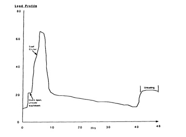
Figure 2. An example of a refrigeration load profile for a beef chiller
The load profile can now be plotted and, for the hypothetical example already discussed, is shown in Figure 2. At the start of the figure the room is running with no product load and with the doors closed. The load then increases when the doors are opened and the room is washed out or possibly unloaded. Warm carcasses are then loaded into the room and the load rapidly reaches the peak product load that occurs at the end of the loading period. Thereafter, the doors are closed and the load rapidly declines. At the end of the chilling cycle the doors are again opened to remove the carcasses and the infiltration load so caused increases. During the chilling period additional peaks occur after defrosts. Note that the plant only runs at its full or peak load for less than 4% of the time. It runs at or above half load for 25% of the time and for over 70% of the time runs at less than a quarter of its design load.
Refrigeration plant capacity
The capacity of the refrigeration plant must now be decided. Will the peak heat load be met? If so the planned chilling times and the specification agreed will be achieved. If not, the desired schedule will not be attained, but there will be a saving in the capital costs of the refrigeration plant and more economical running will be achieved since the plant will be running at less than quarter capacity for over 71% of the time. Large refrigeration plants working at low loads are very inefficient and therefore very costly to run. If a smaller plant is used it will have a smaller turn-down ratio and its efficiency at part load, the majority of time that it will run, will be higher therefore saving operating costs.
There are some possible solutions to the designer’s dilemma. If refrigeration capacity is demanded elsewhere in the plant, but at different times, the provision of a central plant serving both facilities can make use of this diversity. It is therefore important at this stage to look at the refrigeration load profile for the entire plant - there may be blast freezers which are only operated well after the time that the peak chilling load has passed and by careful refrigeration design plant may be installed and shared between both facilities. However; this only applies to a part of the refrigeration plant, the compressors and condensers, and not the evaporators. Another solution is to install a plant that is smaller than needed and recalculate the extended cooling times that will occur, still meeting the chilling/freezing specification. When the refrigeration load increases above that which the refrigeration plant can extract air temperature in the chiller/freezer will rise. As the air temperature rises two things happen; the product load is reduced and the capacity of the refrigeration plant will increase. The effect of these two changes is that after a time a balance is achieved when the load given off by the carcasses is extracted by the plant and cooling can then continue in the normal way until the temperature is reduced back down to its original level. If data were available on cooling during pull-down it would be possible to recalculate the extended cooling periods, check whether these fitted with the other user requirements and still install a refrigeration plant which would meet an agreed specification.
Another option is to spread the loading time of the chiller/freezer over a longer period, and so reduce the peak product loads. However, this normally causes disruption in the planned operation of the abattoir with decreasing productivity, and is therefore rarely used.
Whatever decision is taken, the peak product load that the refrigeration plant is expected to accommodate should be clearly stated in the agreed engineering specification. A load profile should also be given to ensure that the refrigeration designer provides a plant that will run efficiently over the entire product load range.
Relative humidities
The relative humidity in the chill room must also be defined in the engineering specification. When the chiller is empty and the latent heat load is negligible, relative humidity depends upon the evaporation temperature. The wet bulb temperature will slowly be reduced until it approaches evaporation temperature, at which point no more water will be extracted from the room and the humidity will remain stable. As the latent heat load in the room increases, from the loading of warm wet carcasses, the amount of water vapour evaporated increases the relative humidity in the room. The relationship between latent heat load and relative humidity depends upon two factors: the design of the evaporator coil and plant cycling. Only an infinitely deep coil will produce discharged air with a wet bulb temperature equal to the evaporator temperature. During refrigeration plant off-cycles, no water is extracted from the air and the relative humidity will rise, only to be pulled down again when the refrigeration plant is switched back on. Therefore, to obtain a high relative humidity in the room to reduce weight loss during the latter parts of chilling and storage a high evaporation temperature and a large coil area are needed. This ensures that the refrigeration plant runs for only very short periods of time and when it is running it only extracts the minimum amount of water from the air.
Since humidity is normally only important in the latter stages of chilling, when the load on the refrigeration plant is small, relative humidities greater than 90% can be specified. The engineering specification should specify the relative humidity under full sensible heat load, i.e. the lowest hypothetical relative humidity that can be obtained, and also under part load conditions when advantage can be taken of the reduction in load to raise evaporation temperatures in the space.
Ambient Design Conditions
The conditions in the air outside the chiller/freezer must also be defined in the engineering specification. Both the infiltration and fabric loads are dependent on the outside temperature which therefore has an important effect on the capacity of the refrigeration plant. Ambient temperature also affects the capacity of the refrigeration plant because heat must be rejected above this temperature via a cooling tower or condenser. If it is intended that the room should function under all possible ambient conditions, very high ambient wet and dry bulb temperatures must be specified. However, these normally occur only during exceptional circumstances and, only briefly at or soon after midday. For design purposes, temperatures that are not exceeded for more than 2.5% of the total time in the year are normally acceptable and often a figure of 5% is used. Both wet and dry bulb temperatures should be specified giving the option of using an evaporative type of condenser or cooling tower for heat rejection to the atmosphere, which leads to a more efficient and smaller cooling plant.
Defrosts
The occurrence of defrosts should also be specified to avoid the peak periods while still ensuring that during these peak periods the evaporator is clear of ice. It is normal in abattoirs to defrost the evaporators and the chillers at 6 hourly intervals. Although this is often desirable immediately after the peak latent heat load has been removed from the room it is unnecessary during the later stages of cooling and when the room is used as a store. Limiting defrosts can reduce both energy consumption and weight loss during subsequent use and therefore should be included in the engineering specification.
Engineering design summary
The engineering specification should therefore include each of the items shown below:
-
1.Chiller, freezer etc. air temperature, air speed and relative humidity for each product specification (covering complete range) and the time that each of these periods will be operating
-
2.The ambient air temperature: both wet and dry bulb
-
3.The load: peak, average and store
-
4.Infiltration load, i.e. the number of doors and the time they will remain open, under what circumstances and conditions
-
5.Evaporator and condenser temperatures
-
6.All the conditions laid down in the engineering specification can be measured and therefore do not depend upon variation in usage or even abuse of the chiller and should therefore form the basis of a contract.
Procurement
The engineering specification should be sent out to tender. If tenders have been selected for the quality of their equipment and all accept the tender conditions and say they can meet the design and test conditions specified, the lowest tender would normally be chosen. The contractor is normally responsible for the detailed engineering design, construction and commissioning and the only need is to check that this work is carried out in a professional way. His first responsibility is in carrying out the acceptance tests. These test the performance of the refrigeration equipment in terms of the engineering specification and the plant should not be accepted until satisfactory tests have been carried out. The plant can then be handed over and training given to the plant operators in the correct use of the refrigeration equipment. The plant then needs to be commissioned by the factory personnel, systematically increasing throughput until the process tests can be carried out. These ensure that the original process specification in fact achieves the intended results in terms of temperatures, throughputs and yield.
Plant design
Once the engineering specification has been written and agreed the plant design is relatively straight forward. The difficult decisions have already been taken. The details of refrigeration plant design have been laid out in many other text books and will not be repeated here. However, one problem area is specific to carcass chillers and this is the selection of evaporators.
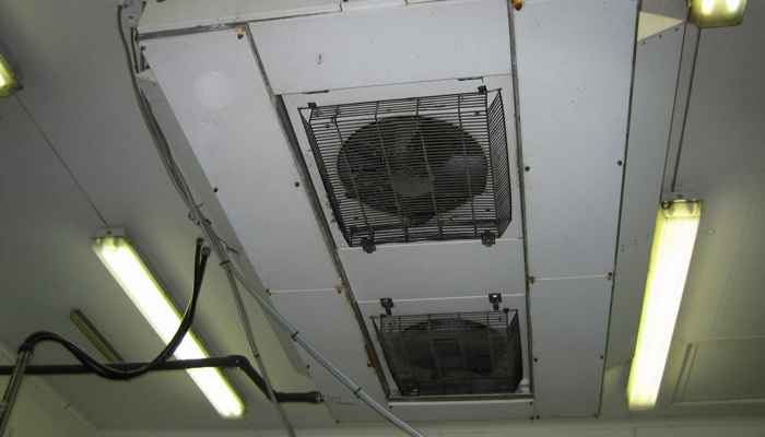
Evaporators
An evaporator has two functions. The first is to remove heat and moisture from the air in order to maintain the correct design conditions. The second is to move air around the room. Standard evaporators are designed for the first function but the second is largely ignored and some evaporator manufacturers do not even publish information on how their evaporators may be used for this purpose. This is partly because air movement in the room depends not only on the evaporator design but also on the shape of the room, position of the beams etc. Some general points follow.
Air movement is controlled by blowing air and not sucking; that means that it will move under the effects of dynamic or static pressure. A moving jet of air will not go on moving forward indefinitely but will be slowed down by the action of friction against solid surfaces and by friction and entrainment of static air adjacent to it. The throw of the jet is the maximum distance that the air will move until it slows to a specific velocity. If the air is thrown under a ceiling or along another solid surface the coriander effect will increase the length of the flow, whereas if the air is thrown out into a void with friction on all sides, mixing and entrainment will slow the jet in a shortened distance. Any beams, light fittings or solid objects in the path of the jet will serve to deflect it and turn it in another direction and therefore have a pronounced effect upon the air movement within the space.
Air can be distributed in a space above the rails, possibly with a false ceiling or via plenums or ducts. Estimates of air movement in a chiller are sometimes based on the cross-sectional area and the volume of air passing through it. Although this gives an average velocity over that cross-sectional area it is often very deceptive since this velocity rarely occurs around the carcasses. Such calculations are more useful in designing blast freezers when a horizontal flow of air moves through a tunnel. They may sometimes be used in pre-chillers which function as blast chillers, similar to blast freezers with high air velocity and a large refrigeration load and consequently a large column of air movement.
In Figure 3 several ways of distributing air from the evaporators around a chiller are shown. Each uses the void above the rail for primary distribution. As air is blown under the ceiling it is drawn across by the coriander effect towards the far wall. On the way air is entrained from around the carcasses and drawn into the jet until the jet expands and starts hitting the rails. This deflects a proportion of air down around and through the carcasses. If the velocity of the jet is more than the maximum velocity required around the carcasses by the time it reaches the far wall (throw), or another jet, then a down draught will occur at that point, moving to the floor and then in turn deflected back across the floor.
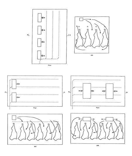
Figure 3. Examples of air movement produced by different evaporator positions
Some problems that occur arise from a conflict between the two functions of the evaporator. If it is selected to meet the peak product load, the air velocities created can be excessive, i.e. the throw will be greater than the distance from the evaporator face to a wall or jet facing it. Sometimes the situation is reversed, i.e. the throw is too small. There are several possible solutions:
-
1.The evaporator selection can be changed to alter the discharge velocity
-
2.The fans can be altered from draw through to blow through or vice versa
-
3.The discharge angle of the jet can be altered
-
4.The position of the evaporator can be altered
-
5.In the final design a combination of the above can be used.
However, in the authors’ opinion, although there is considerable information relating to air movement there is still insufficient information available to design a uniform air velocity around all carcasses and it must be recognised there will be a range of air velocities in the room and hence a range of cooling conditions.
The largest refrigeration load during carcass storage and in the latter stages of cooling is that of the evaporator fans. These are selected to extract the peak cooling load where high velocities are needed. There are several options available to the designer to reduce excessively high air velocities during the second stage of chilling and during storage. The first is to use two-speed motors; another is to switch off a number of fans on each evaporator unit or even a number of the units. Although this will cause an uneven air distribution within the store, it has often proved adequate to maintain temperatures throughout the room during storage. Often the conflict is so great that such solutions are not possible. In those circumstances it would probably be better to design a separate refrigeration system for use when the chiller is used as a store. For instance, one refrigeration plant is designed for chilling a separate plant with a sock diffuser system used for storage, giving ideal velocities during both functions. The smaller refrigeration plant installed for storage will operate much nearer it maximum load for long periods and hence be far more efficient than the much large chilling plant operated under the same circumstances.
Things to remember
-
1)The performance of refrigeration systems is a major source of conflict between users and refrigeration contractors. The adoption of the approach outlined in this chapter should avoid these conflicts. If performance problems occur then the approach will clearly identify which partner is responsible for sorting out the problem.
-
2)A user must accept the responsibility for the process specification. They must clearly identify what they wish to achieve and take into account their expansion plans. Outside input may help them clarify their requirements and options but the final decision is theirs.
-
3)From a clearly defined process specification an engineering specification can be written which defined the requirements in terms of the conditions that have to be produced within the refrigerated enclosure. It will define space limitations, etc., the tests to be carried out before acceptance and any monitoring/control instrumentation.
-
4)The process specification and its development into an engineering specification are the critical steps in obtaining a system that works. The rest of the procedure should follow automatically. However, the cost factor should not be forgotten. Often the initial quotations are outside the users budget and during discussions cost savings are agreed. All to often there is an implied change to the engineering and consequently the process specification. Unless this is formally recognised and the specifications amended to take into account the change a source of conflict in the future has been established.